Overview
This project is primarily focused on working with 3D objects, from plotting the Bezier curves and surfaces (Section I) , to performing operations on meshes for upsampling (Section II) , and in the last part, applying shading effects to objects (Section III). Overall, I spent the most time on Part 6 (upsampling), but it's also the most interesting part of the whole project. It's interesting to know that pre-splitting or pre-flipping can sometimes make big differences in upsampled objects. Depending on whether you want to accentuate or smooth edges, you can perform different preprocessings to get the desired result. In terms of programming skills, I learned the importance of writing test cases to make sure each small chunk of code is correct before moving on. Part 6 was hard to debug in the sense that it was related to Part 4, and 5.
Section I: Bezier Curves and Surfaces
Part 1: Bezier curves with 1D de Casteljau subdivision
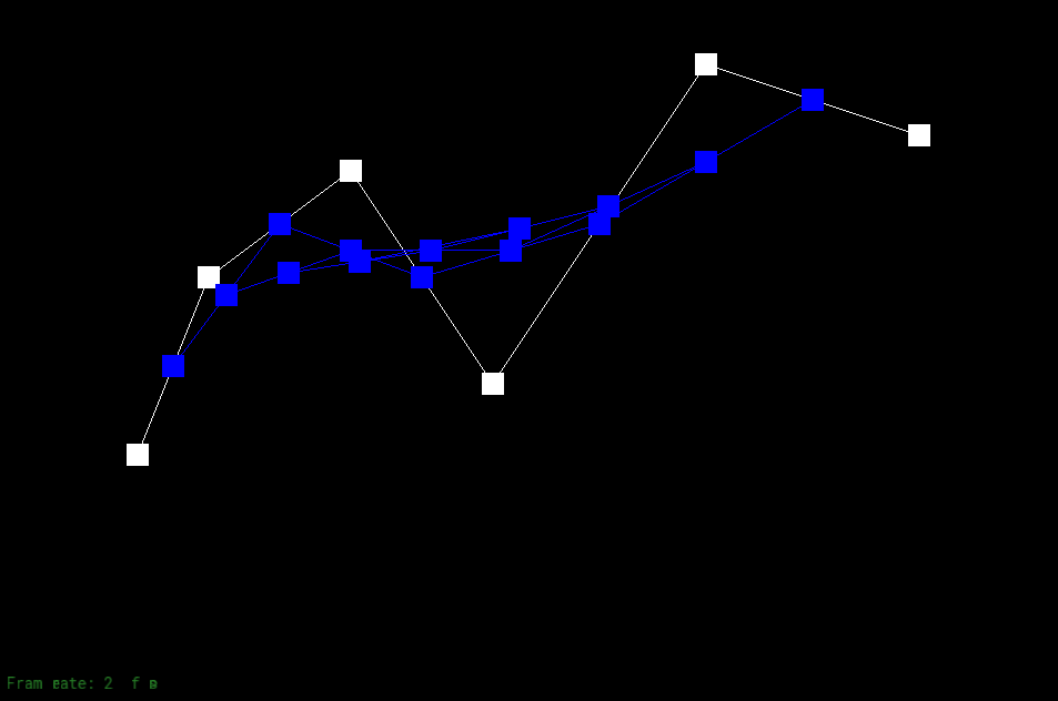
The de Casteijau's algorithm takes two adjacent vertices and return a midpoint according to a ratio \(t:(1-t)\). I then store all of the intermediate control points into a 2D vector, with each level being the result of one iteration.
The following shows the iterative process of performing de Casteijau's algorithm. In Figure 1-7, the curve is drawn in green. Bezier curves make it easy to modify the shape of the curve through control points and ratio. Figure 1-8 is an example of moving the second control point from the left to a new position and altering the ratio so that \( t\) is smaller.
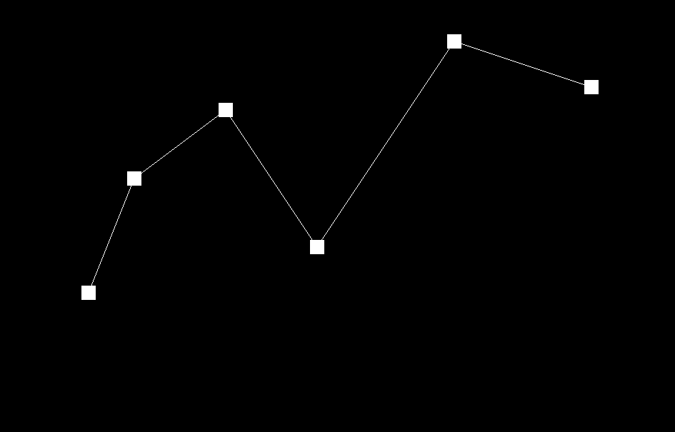
Original 6 points. |
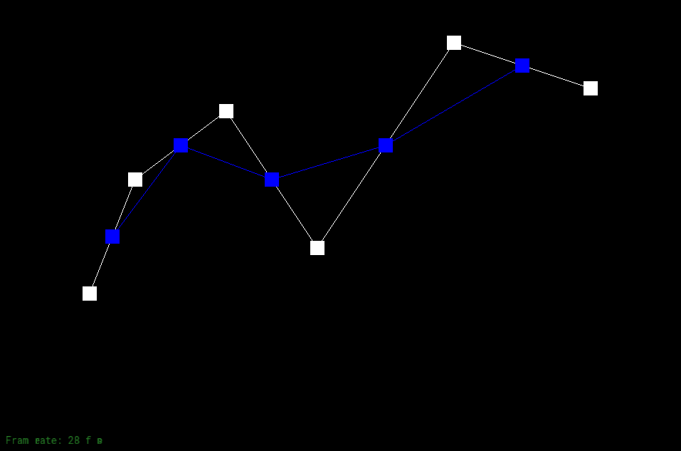
1st Iteration. |

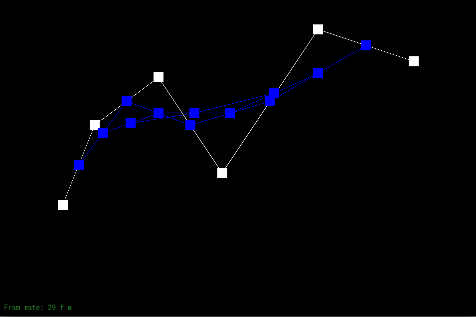
2nd Iteration. |
3rd Iteration. |
4th Iteration. |

5th Iteration. |
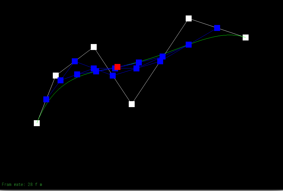
Drawing the curve. |
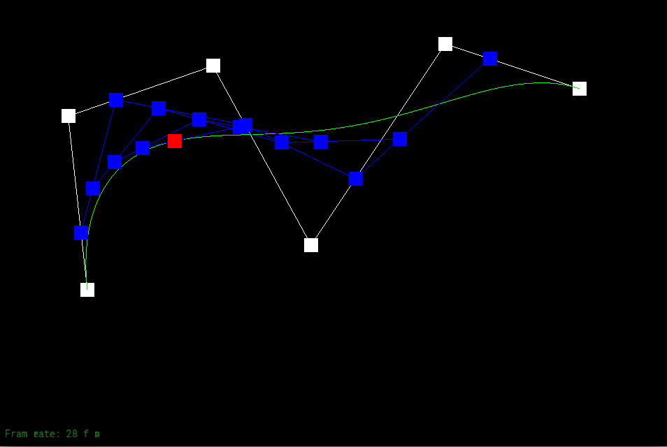
Modifications made to the position of the points and the ratio t. |
Debugging journey:
At first, I was grouping the points two by two with no overlapping. The bug was easy to catch once I step through each iteration and realize it's missing some of the midpoints.
Part 2: Bezier surfaces with separable 1D de Casteljau subdivision
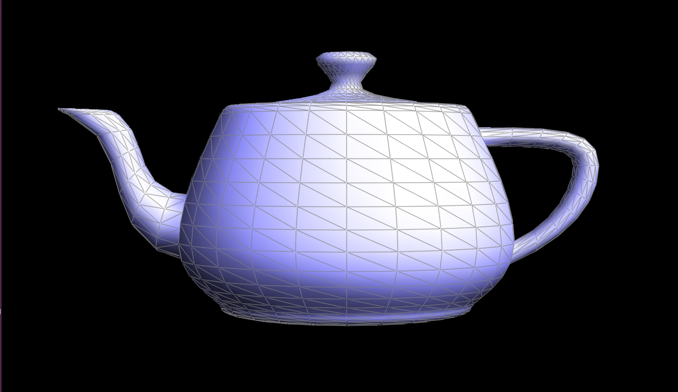
Given a 2D array of points, to perform de Casteljau's algorithm to Bezier surface, first perform de Casteljau's algorithm to each row. Each row will be reduced to contain only one point. Once the column of points is obtained, perform de Casteljau's algorithm again to get one point.
In order to make calculation simplier. I first implemented a function that returns a point from a vector of points using the de Casteljau's algorithm. I then take the 2D array of points and apply each row to the 1D function.

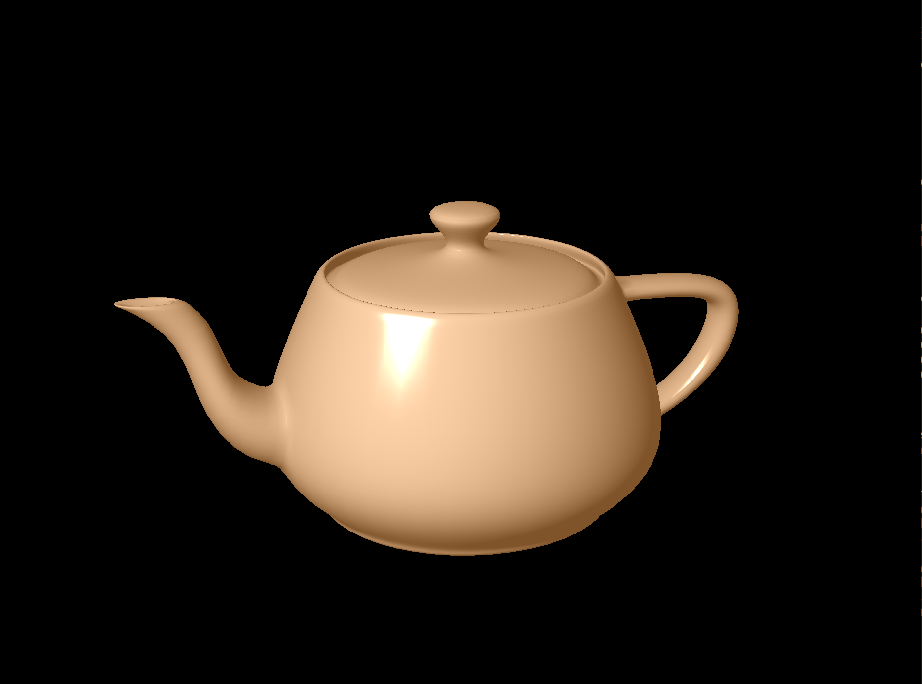
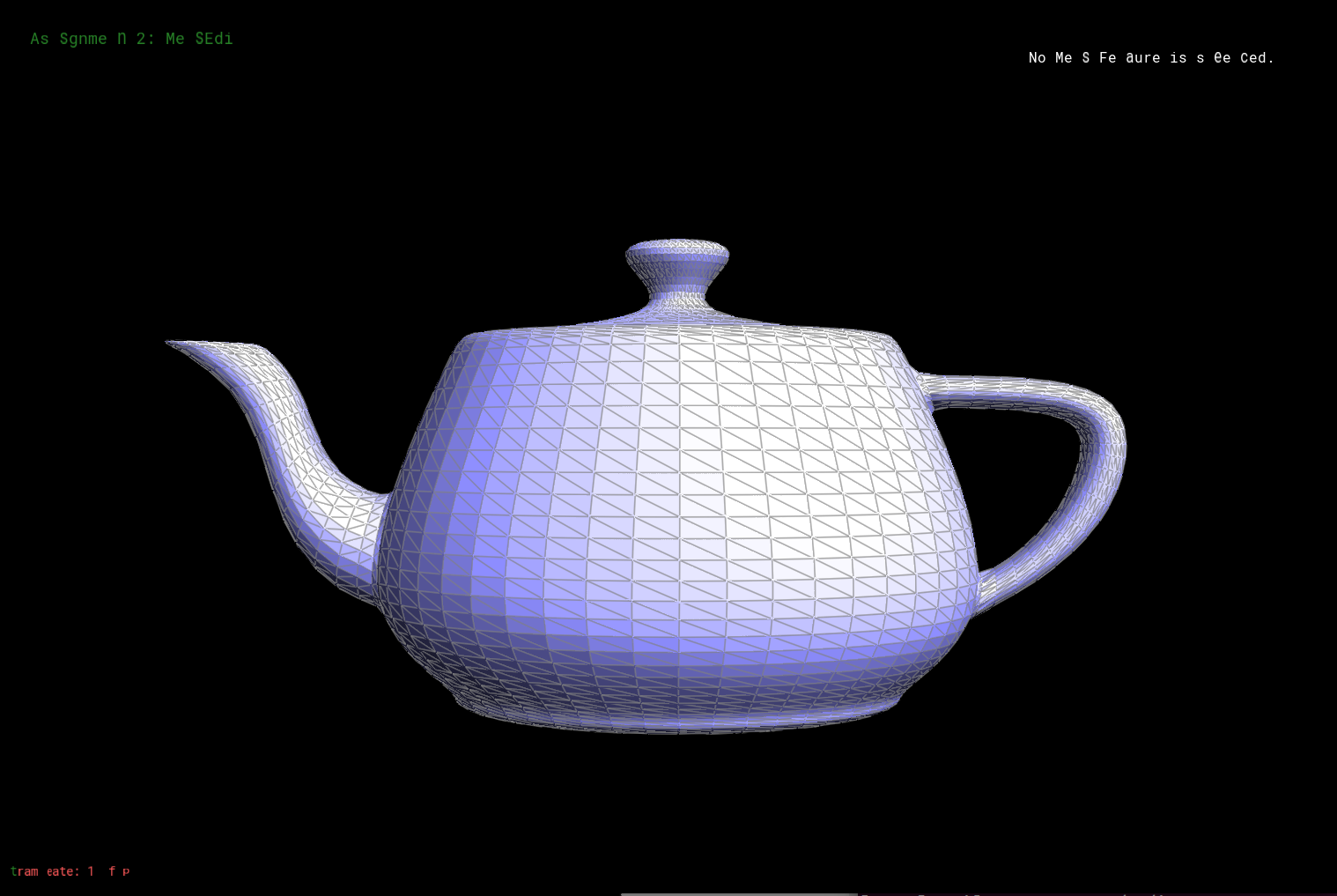
Teapot rendered from beizer surface. |
Section II: Sampling
Part 3: Average normals for half-edge meshes
The idea is to sum the normal vectors of the surrounding areas and then normalize the resulting vector.
The most important part when implementing this section is to make sure to traverse through all the faces surrounding a vertex. A carefully thought while loop is able to achieve this. Once the summation of all the normal vectors from surrounding is achieved, the last step is to make sure the resulting normal vector is normalized.
In the end, it creates a more "continuous" surface.

Part 4: Half-edge flip
Flipping an edge in a mesh is considered one of the elementary operations.
There are two steps to this part. The first step is to declare variables of the original mesh. This includes vertices, edges, halfedges, and faces. The second step is to reassign the old elements (verties, edges, halfedges, and faces) found in the first step to new locations according to the result of flipping.

Debugging journey: The surrounding edges of the meshes are the most tricky. It took me awhile to debug because I originally thought the faces that the outside halfedges point to are also within the current mesh. It was fairly simple to implement after I figure out that halfedges on the outside are not changed after the flip.
Part 5: Half-edge split
Implementation of this part is pretty similar to Part 4. The main difference is the allocation of new elements in the first step. This is because there are more halfedges, edges, vertices, and faces after splitting.
Debugging journey:
I was able to perform split operations after implementing the procedure mentioned above. However, I came back to this section after realizing that I need a way to track old or new vertices and edges when working on part 6 (upsampling). I then added three more lines of code. One for setting the isNew attribute for the newly created vertex to true, and two for setting two newly created edges' isNew attribute to true.
Part 6: Loop subdivision for mesh upsampling
There are five steps in performing loop subdivision.
Part 1. Iterate through all the vertices and set the vertices isNew attribute to false to specifiy these as the original vertices. Calculate the new position for these vertices after upsampling and store the value in the vertex's newPostion attribute.
Part 2. Iterate through all the edges and set the edges isNew attribute to false to spcify these are the original edges. Next, calculate the position value for the new vertex resulted from splitting a mesh and store it in edge's newPosition attribute. This position will be used later in Part 3.
Part 3. Split every edge in the mesh. The splitEdge function returns a VertexIter type. We can set the newPosition attribute of this VertexIter type to the edge's newPosition obtained from part 2.
Part 4. Flip edges that are connected to an old edge and a new edge. The trickest part is to make sure that we are not flipping edges that are on the original edge even though technically these newly splitted edges are also in between an old and new edge.
Part 5. Iterate through all the vertices and assign newPosition to position.
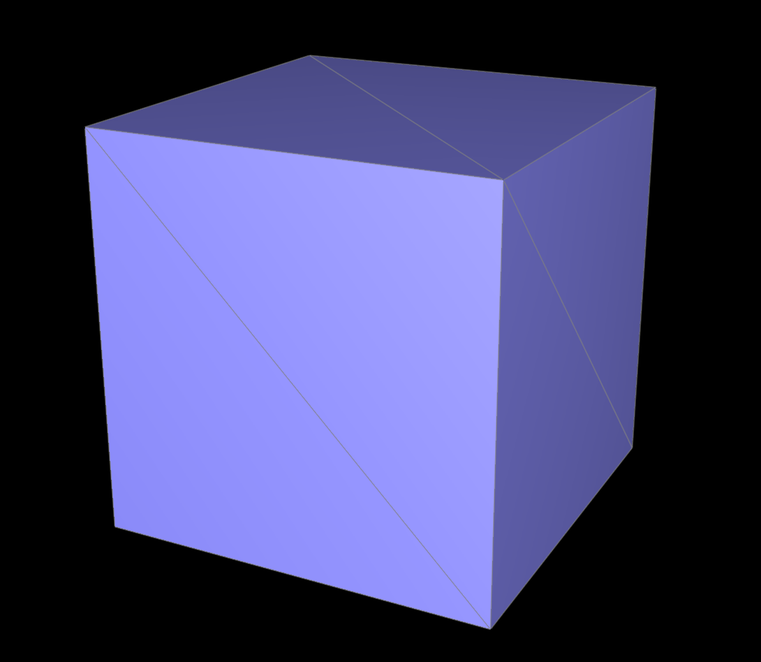
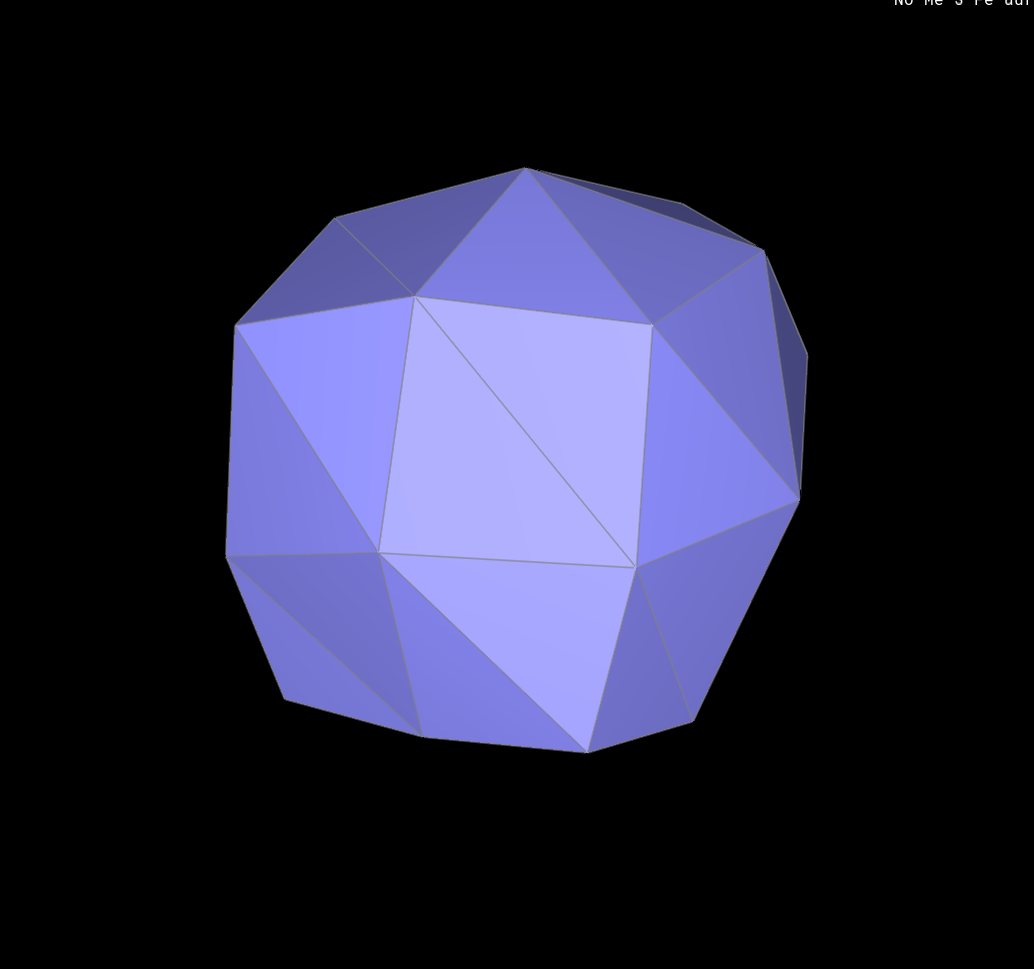
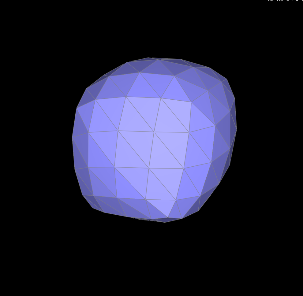
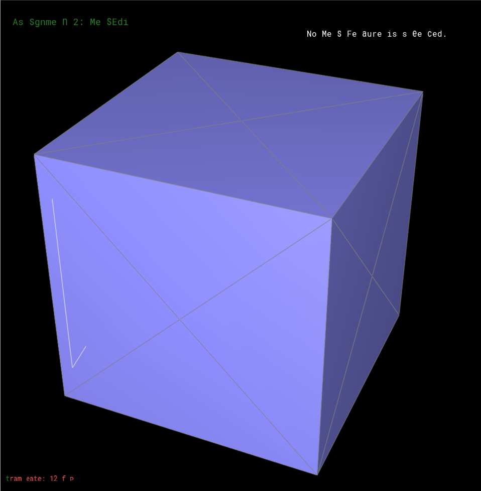
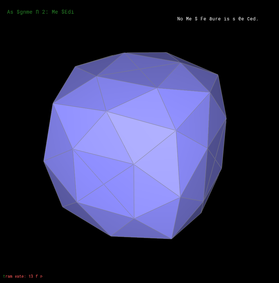
Upsampling cube.dae
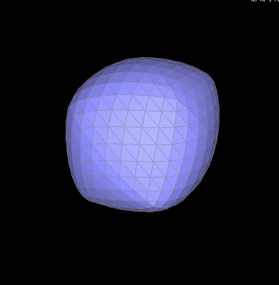
After several iteration of upsampling, the sharp corners and edges causes the object to sample assymetric. (Figure 6-4) The upsampled object has "bumps" at positions where there were originally sharp and edges.
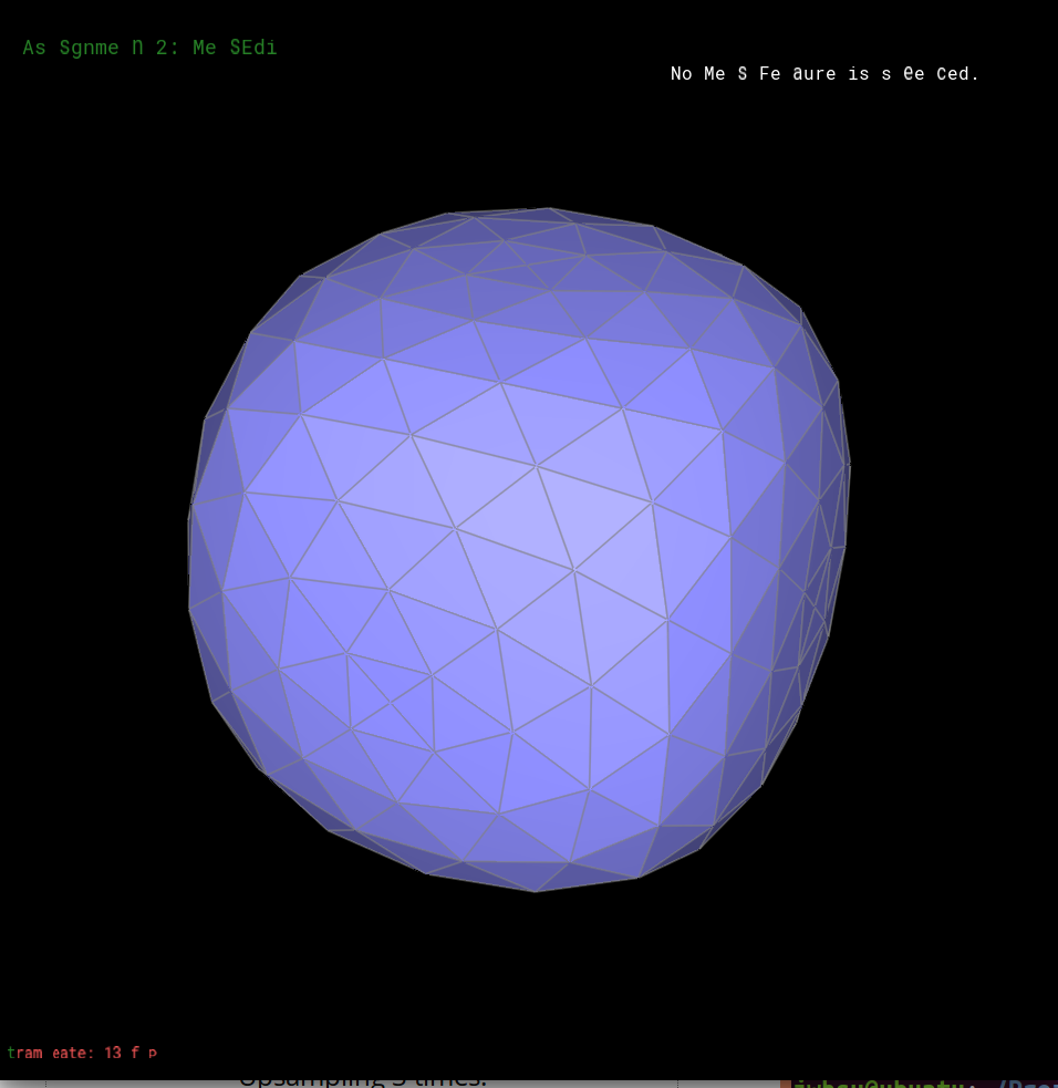
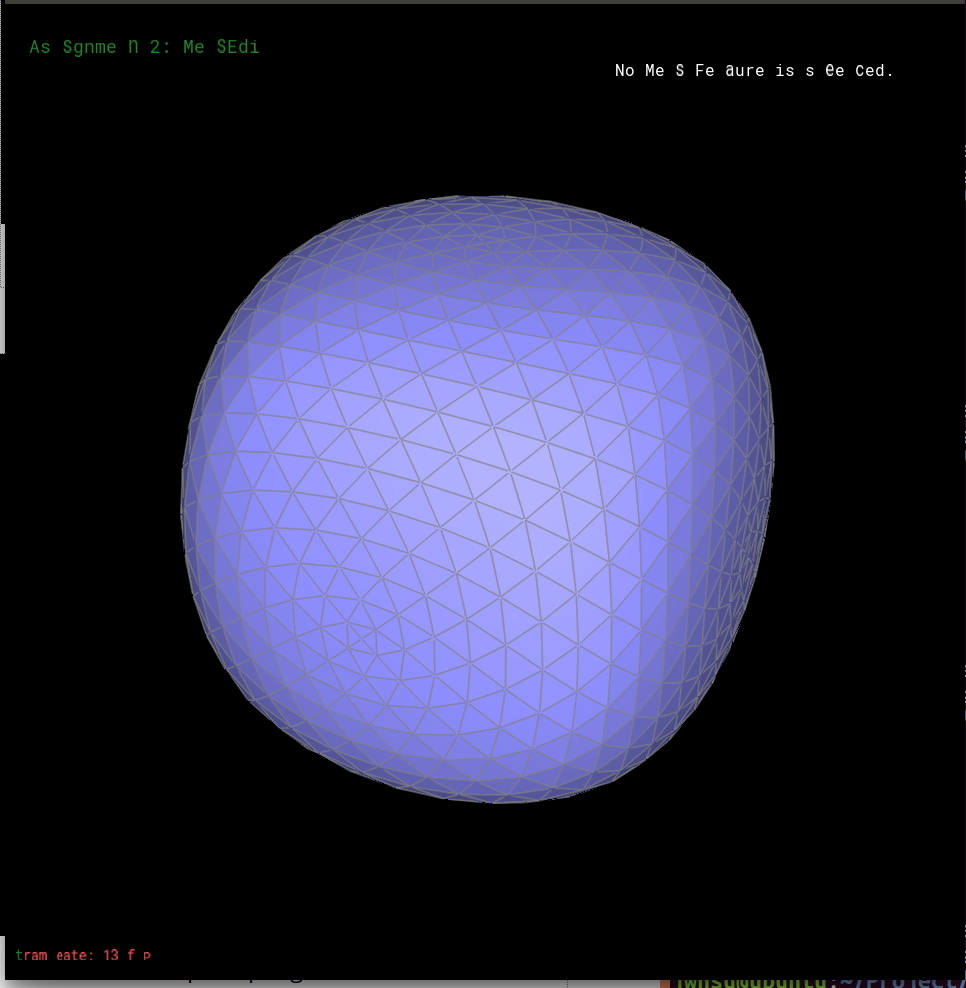
Upsampling cube.dae along with pre-splitting.
In orer to smooth out the "bumps" mentioned above, we can try to lessen the effect by pre-splitting some of the edges.
If I try to split each face of the cube before upsampling, then the object after four upsampling has smoother edges and corners. The result is also more symmetric than the one above. By splitting some of the meshes, the upsampling process will calcualte more sample points and hence produce a more symmetric object.
A couple more upsampling examples
Teapot


Cute Cow
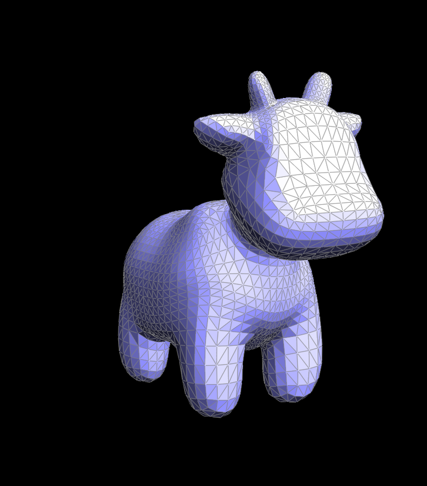
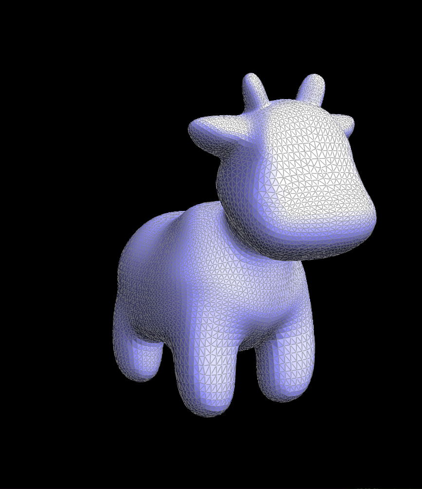
Note: The meshes are pretty detailed after just 1 upsampling iteration.
Debuggin Journey: Debugging part 6 took me the greatest amount of time. In the beginning, I was having trouble with getting the correct connection. I fixed that by moving the messy code to update isNew attributes for vertices and edges from the upsampling function to the split function. Doing so proved to be more simpler, since I don't need to perform tricky edge tracking while loops. This solved the connection problem. I didn' realize taht Iw as still having problem until I ran upsampling on the cube, where I started to see some points never got updated to the new position. At first I was suspecting there was something wrong with my flipping and splitting function so I spent a lot of time double, triple and quaduple checking that the pointers are pointing to the right places. I end up using print statements to print the updated positions and finally found out after hours of debugging that I had declare the variable u as an int. This was the reason that the positions of some vertices weren't updating correctly. Once I fix this, everything works perfectly.
Section III: Shaders
Part 7: Fun with shaders
This section uses a shading language called the GLSL.
The calculation process was fairly simple after getting familiar with the slightly different syntax in GLSL.